


Dedicated products designed by EFER allow endoscopic implementation, in remote access locations, of measurement procedures, micro-blending, and non-destructive testing.
- ENDO FPI SYSTEM
- ENDO BLEND SYSTEM
- BLADE EROSION
- NUCLEAR FUEL
- HEAT EXCHANGERS
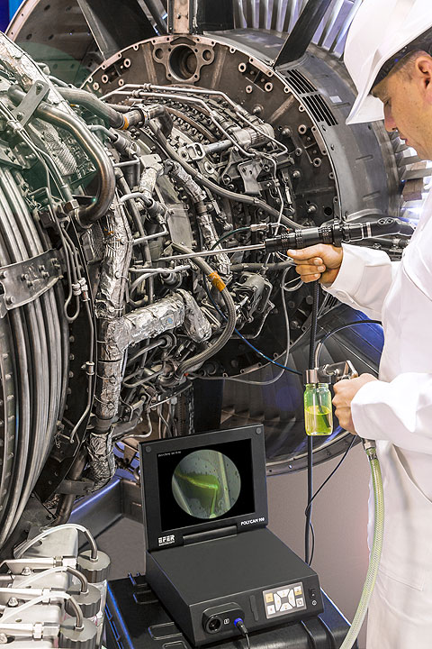
ENDOSCOPIC FLUORESCENT PENETRANT INSPECTION SYSTEM
The system allows to resolve doubts arising during routine endoscopic inspections posed by suspicious indications. It is also commonly used to guarantee the absence of residual cracks after blade-blending.
In the first operation phase, carried out under white light endoscopy, the various chemicals required for FPI are projected on the area of interest.
This phase is followed by endoscopic inspection under UV light of the FPI-processed area.
The endoscopic FPI system developed by EFER ENDOSCOPY typically comprises the following items:
• FPI chemicals case
• A range of rigid endoscopic tools typically used for inspecting low pressure turbine and high pressure compressor stages
• A range of flexible endoscopic tools better suited for inspecting the low pressure compressor stages
• VEGA 900 UV ultra-violet/white light source
• MUCAM T900 camera
• POLYCAM 900 visualisation and recording unit
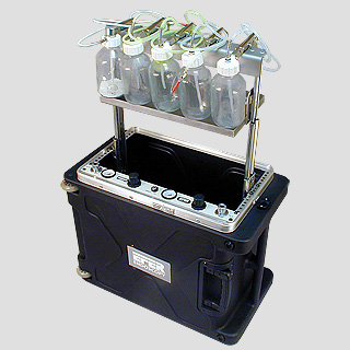
The case comprises five jars containing the various materials necessary for an FPI process, and implements an air compressor (or alternatively a compressed air input) which serves to both pressurise the jars and deliver compressed air to the endoscopic tool. Each jar has its own spray gun allowing to inject its chemical into a capillary tube inserted in the tool.
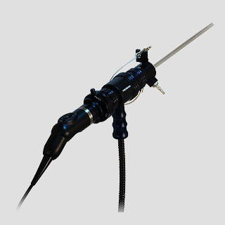
Tubular tool made up of a first internal tube which receives a capillary tube, a second tube for an endoscope, and a third one for delivering compressed air on the endoscope distal lens. This tool has an articulated distal tip, controlled by rotating ring on handle, to position the capillary tube near the inspection zone.
The tool works with its associated UV endoscope which is connected to both a VEGA 900 UV light source by liquid light cable, and MUCAM T900 camera with POLYCAM 900 operating unit.
ARGUS UV 900 K probe of 6 or 8 mm diameter with axial vision and UV illumination, having an internal channel whose proximal gate receives both a capillary tube and compressed air serving to clean the probe distal lens. This probe has an integrated umbilical cable which connects to a VEGA 900 UV light source and a POLYCAM 900 operating unit.
 VIDEO
VIDEO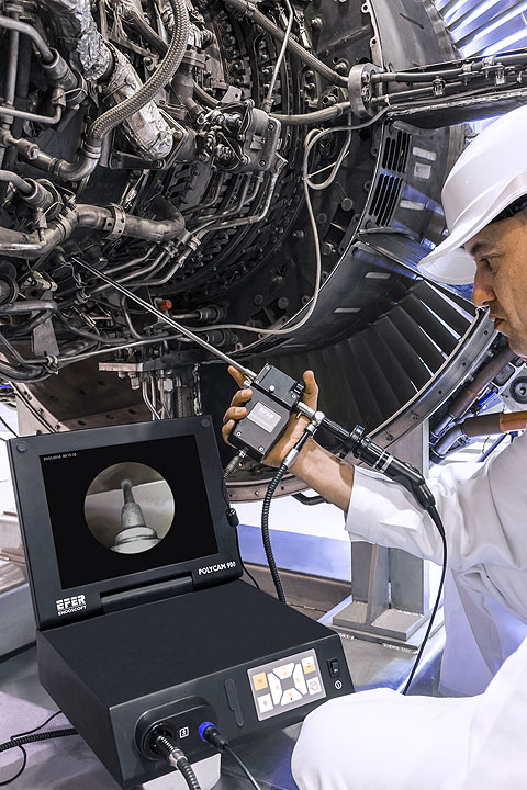
One of the main sources of incidents in aircraft engines, damage by ingestion of foreign bodies, is generally found on blade leading edges of compressor stages, typically in the form of impacts.
Investigation of these defects, possibly involving measurement, is carried out using an ARGUS 900 probe associated to a TIVE 900 operating unit.
Depending on the number and dimension of these impacts, engine removal for subsequent blade replacement in shop may be necessary. Alternatively, the significantly more economical solution of filing or grinding these defects with the engine remaining on-wing, commonly known as “Blending”, is available.
The endoscopic blending system designed by EFER comprises the following devices:
• ENDOGRINDER endoscopic tool
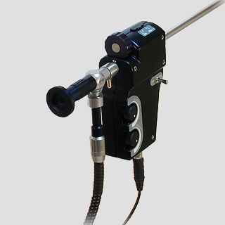
• PIKO specific rigid videoendoscopic probe
• A POLYCAM 900 video-light operating unit
A specific optical endoscope coupled with a MUCAM T900 may be used as an alternative to the PIKO video probe.
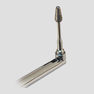
The tool comprises:
• A proximal handle with various operational controls and which houses the motor
• A cylindrical tube which houses videoendoscopic probe, distal tip articulation connecting rods, and drive belt linking motor to distal tip pulleys
• An articulating distal tip which receives interchangeable grinding, brushing and polishing tools
The handle has the following:
• Gate through which the tool-specific video probe is inserted then fastened
• 12 V power input
• ON / OFF switch
• Distal tip articulation control
• Drive belt tension control
• Torque variation control
• Distal tool speed variation control
• Distal tip articulation indicator
Optical (field and direction of view) and mechanical (diameter, length) characteristics: specific to the grinding tool
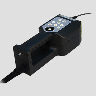
• Compact proximal handle with lock and 2-button keypad to control FREEZE and RECORD functions of the POLYCAM 900 unit associated to probe
• Integral video-light cable connectable to the POLYCAM 900 unit

BLADE EROSION MEASUREMENT SYSTEM
Defects likely to affect integrity of blade leading edges on a helicopter turbine arise from two types of incidents:
• Foreign body ingestion by turbine can result in material loss from blade leading edges. Measurement of this damage can be achieved using an ARGUS 900 probe fitted with a distal stereo tip, connected to a TIVE 900 unit running the 3DSIZER tridimensional software. Depending on the number and dimensions of these defects, an on-wing “Blending” operation can be carried out or decision is made for engine removal leading to blade replacement in shop.
• Ingestion by the turbine of a multitude of abrasive particles can in itself result in regular erosion of leading edges of all blades on the engine stage. This is essentially seen on helicopter engines and particularly military machines operating in desert conditions. In this case the “stereo” measurement method is not capable of measuring the degree of blade erosion.
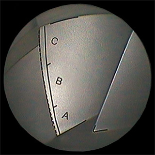
The solution developed by EFER involves modelling a non-eroded blade and then creating a graticule representation which also includes erosion level limits, beyond which an engine removal is necessary. During turbine inspection, this graticule is overlayed on the video image of eroded blades, allowing immediate go / no-go decision.
The equipment developed by EFER and required for such inspection comprises a HTB 900 video probe, strictly specific to the engine stage, associated with its support tool allowing to precisely position the probe and a POLYCAM 900 operating unit.
• Characteristics specific to engine stage:
– Mechanical (diameter/length)
– Optical (field and direction of view)
– Dedicated graticule integrated in probe
• Probe rotation control
• Focus adjustment control
• Graticule rotation control
• Integral video-light cable for connectable to the POLYCAM 900 unit
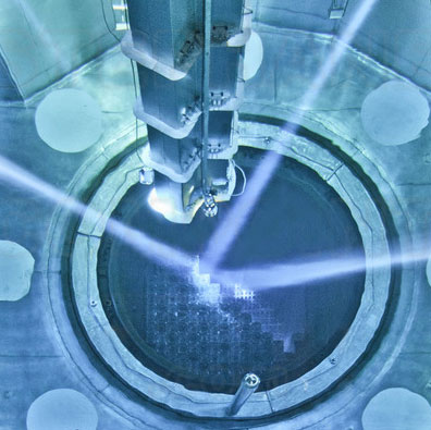
NUCLEAR POWERPLANT FUEL ASSEMBLY GRID INSPECTION EQUIPMENT
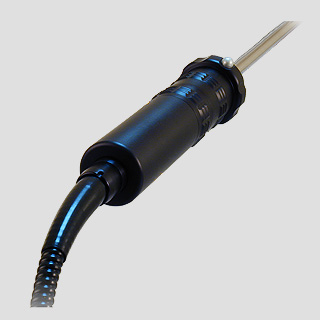
Such radiation-resistant probe is made up of:
• A distal segment comprising a radiation-resistant, quartz-technology fiberscopic probe. This long length probe can have either axial or lateral viewing and implements distal LED lighting
• A waterproof PINCAM 900 endoscopic camera having an opto-electrical interface allowing connection to fiberscopic probe proximal end
• A 30 m length umbilical cable
• An operating unit such as the FLASHPACK 900

STEAM GENERATOR AND CONDENSOR INSPECTION EQUIPMENT
Developed by EFER in lengths up to 30 m, probes responding to this application are summarized below:
| TUBE ASSEMBLIES WITH BENDS | 12 mm diameter JUMBOCAM probe |
| TUBE ASSEMBLIES WITHOUT BENDS | 12 mm diameter JUMBOCAM probe |
| Small diameter rotating lateral view TURN EXPLORATOR probe | |
| 28 mm diameter axial view CAM 28 EXPLORATOR probe | |
| 28 mm diameter rotating lateral view TURN 28 EXPLORATOR probe | |
| 28 mm diameter rotating double-view TWIN 28 EXPLORATOR probe |
All probes are operated using a TIVE 900 unit and EXPLORATOR remote control, and can be stowed in the TR 30 operating reel.
The TWIN 28 EXPLORATOR probe provides the added advantage of allowing simultaneous rapid axial inspection and expert lateral viewing of tube inner surfaces.